Operating
Temperature - 0 to 60 Deg C (32 to 140 Deg F)
Humidity
- 5% to 95% (non-condensing)
Line
Voltage to Transformer - 100-125 VAC, 50/60 Hz
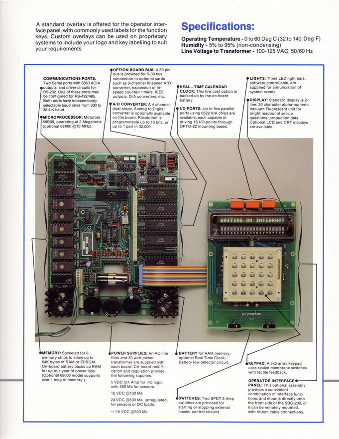
Two
Serial ports with 6850 ACIA outputs, and driver circuits for RS-232. One of
these ports may be configured for RS-422/485. Both ports have independently
selectable baud rates from 300 to 38.4 K baud.
Motorola
681309, operating at 2 Megahertz (optional 68000 @10 MHz).
A
30 pin bus is provided for S-30 bus connection to optional cards such as
8-channel hi-speed A/D con verter, expansion of hispeed counter/ timers, IEEE
outputs, D/A converters, etc.
A
4 channel, dual-slope, Analog to Digital converter is optionally available on
the board. Resolution is programmable up to 15 bits, or up to 1 part in
32,000.
This
low cost option is backed up by the on board battery.
Up
to five parallel ports using 6522 VIA chips are available, each capable of
driving 16 1/0 points through OPTO-22 mounting bases.
Three
LED light bars, software controllable, are supplied for annunciation of system
events.
Standard
display is 2line, 20 character alpha-numeric Vacuum Fluorescent unit for bright
readout of set-up questions, production data. Optional LCD and CRT displays are
available.
Socketed
for 8 memory chips to allow up to 64K bytes of RAM or EPROM. On-board battery
backs up RAM for up to a year of power loss. (Optional 68000 model supports over
1 meg of memory.)
An
AC line filter and 30 watt power transformer are supplied with each board.
On-board rectification and regulation provide the following supplies:
5
VDC @1 Amp for 1/0 logic, with 250 Ma for sensors.
12
VDC @100 Ma
24
VDC @500 Ma, unregulated, for sensors or DC loads.
+/-15
VDC @500 Ma
For
RAM memory, optional Real Time Clock. Battery low detector circuit.
Two
SPDT 5 Amp switches are provided for starting or stopping external master
control circuits.
A
5x5 array keypad uses sealed membrane switches with tactile feedback.
This
optional assembly provides a convenient combination of interface functions, and
mounts directly onto the front side of the SBC-200, or it can be remotely
mounted, with ribbon cable connections.